
Still overestimating my ability to get things done. No rides in Bridget yet but I did get the coolant lines squared away, including what turned out to be a tricky rear hanger system.

Last week I dry started Bridget for about five seconds with no coolant. This week I endeavored to hook up all the coolant lines. Almost made it. There was a lot to do.
First, after work a couple nights last week, I cut and connected my expensive, shiny stainless flexi-hose to the engine and the high side gap. But before I could do that I had to take out some nasty saw-flash from the right side pipe.
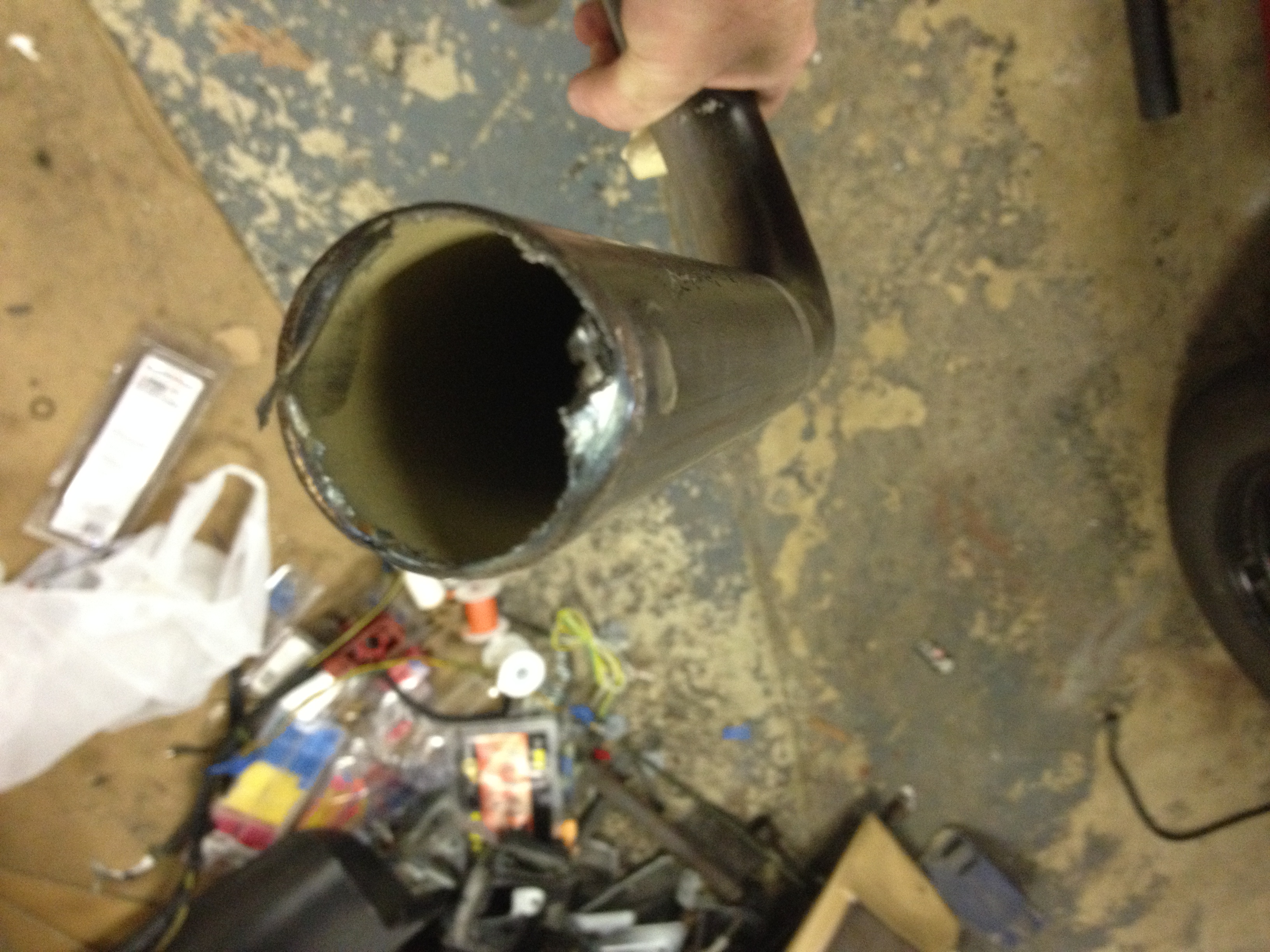

A little grinding and wire wheeling took care of that. Then it was time for the engine hoses.

That hose clamp seemingly doing nothing in the middle of the hard pipe is a custom hanger. There’s a rubber hanger donut captured inside it–muffler guys put that there. Seems pretty good, but I don’t know yet whether it’s brilliant or idiotic. Might work better without the rubber bit.
Anyway, the SS stuff went together without any problem, but the hard lines over the axles were loose. That’s where the real creativity had to occur.

 With that part squared away I turned my attention to the rear hangers. Originally I’d envisioned a simple rubber block bolted to the plate where the jack point was and a muffler clamp on the pipe. But Mike “improved” my concept by taking the hard pipe all the way up and over the axle shafts, then leaving an eight-inch gap between that pipe and the main one that goes to the front. He installed rubber flex hoses in the gaps, and left them loose.
The flex hoses are right where the last hanger wants to be.
I pondered this one for quite a while. Finally decided to cut lengths of 2 1/2-inch exhaust pipe and “cradle” the rubber hose bits inside.
I drilled a hole near the middle of each pipe and put a bolt through with a nut on the outside to hold it steady. Drilled through the plate and floor where the bolt wanted to be when the rubber hose was inside the tube. Then a lock nut with integral washer on that.
The 2.5-inch pipe is big enough to hold the rubber hose and the clamp that goes around it. I cut another rubber hose and wrapped it around the outside of the hose to keep if from rubbing and tighten it up. Seems to hold just right and looks, from a distance, like some sort of exhaust resonator (see the first photo, above).
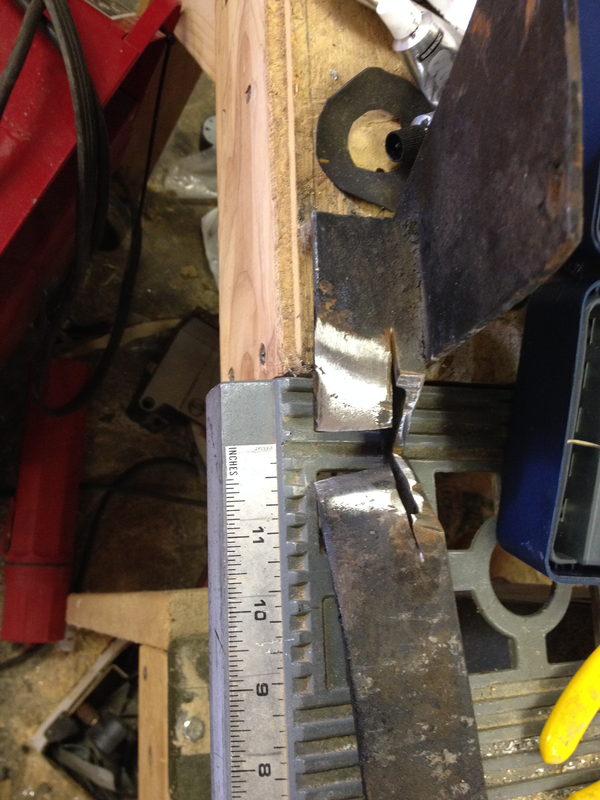
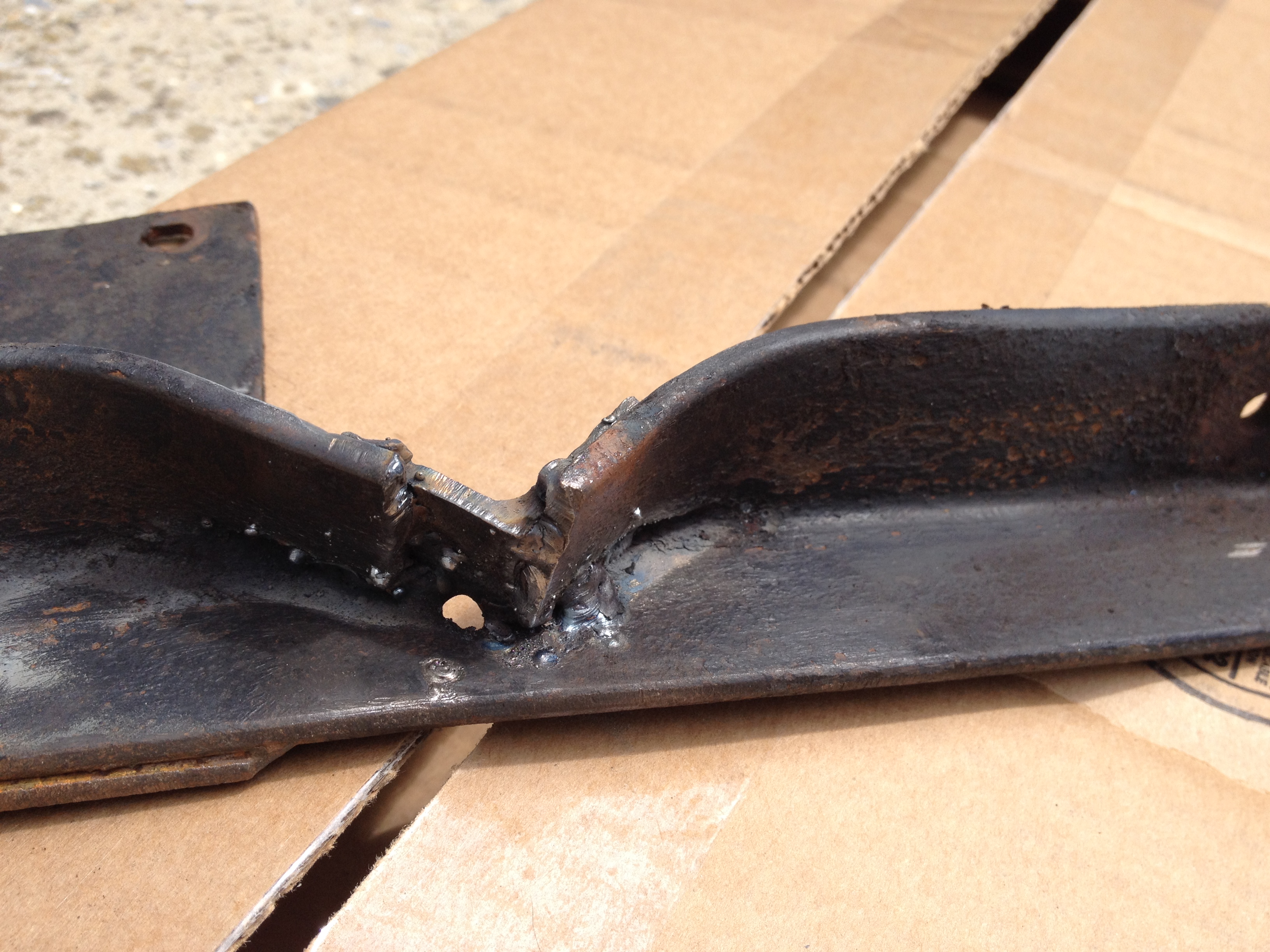
Next I put my crossmember back together.
Months ago I pulled it and V’d it at each end to make room for the coolant pipes. Here’s how it looked this morning:
 I dug out a couple bits of angle steel I’d cut when I was making the trans mounts and tried them for fit.

Good enough. And . . .
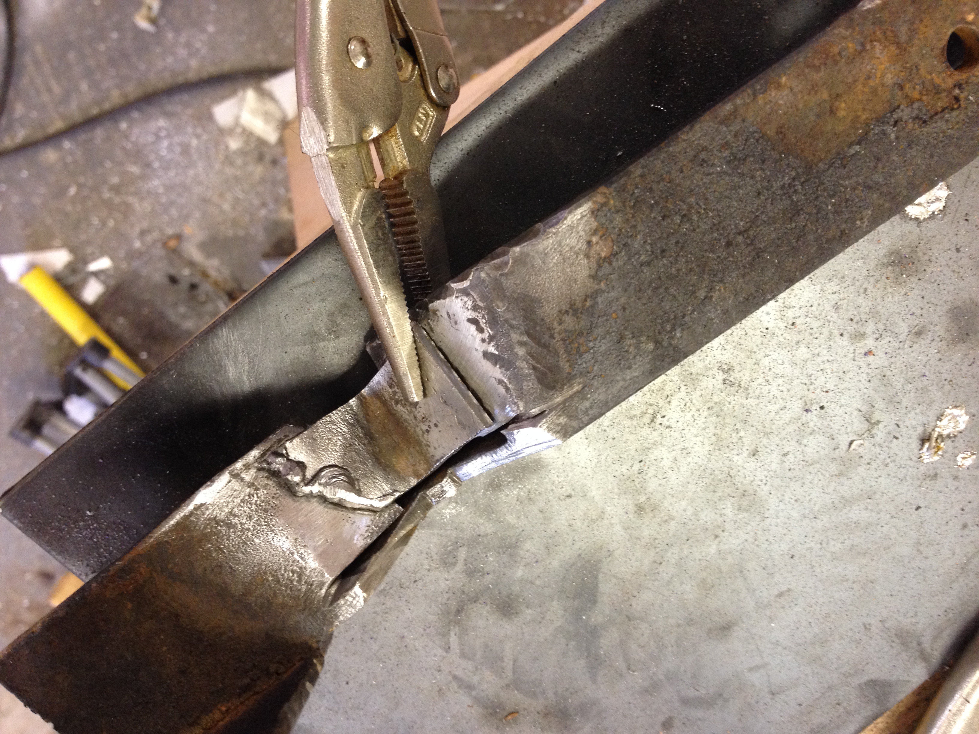
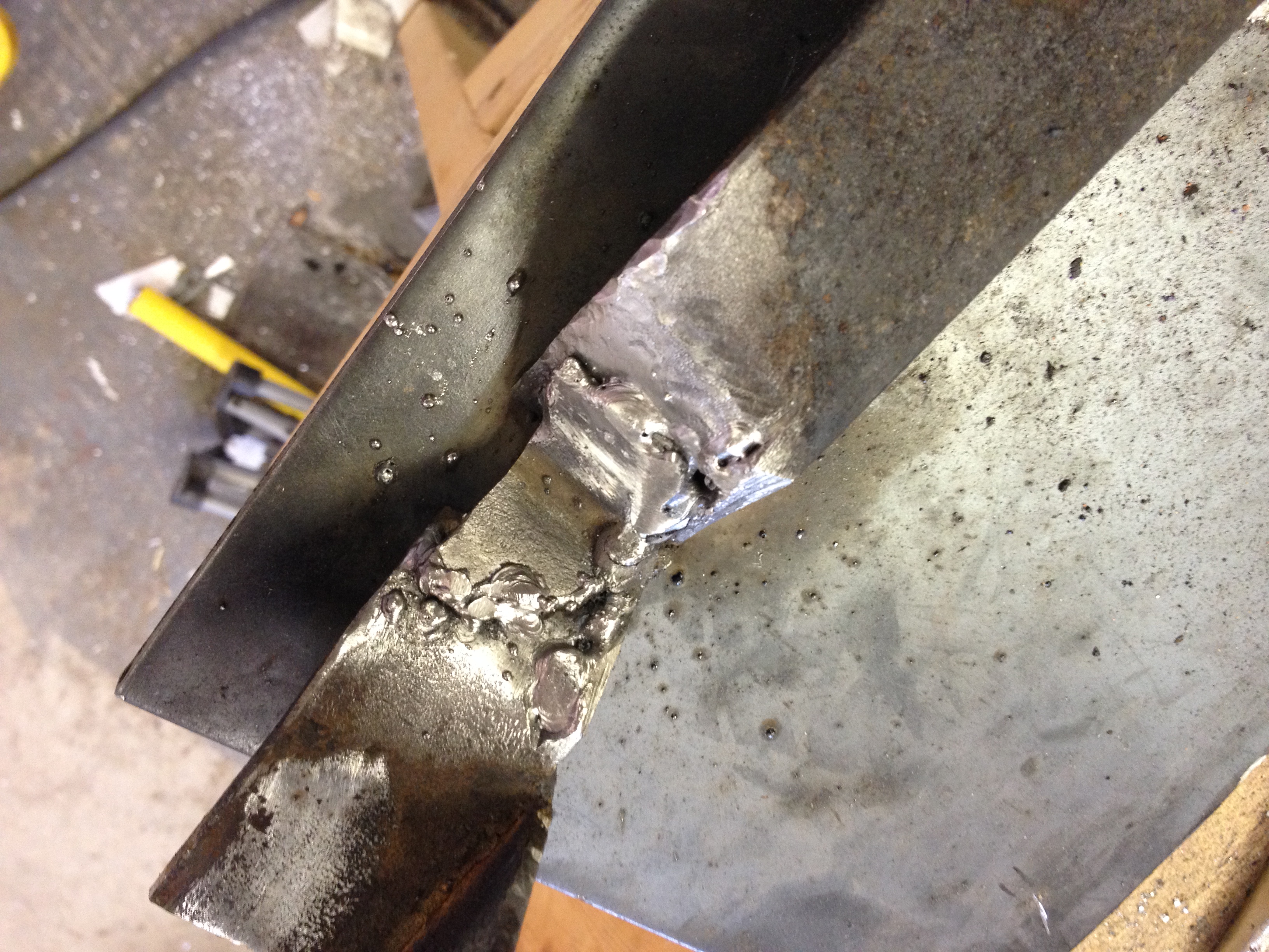

 The crossmember is mostly straight now too. So that’s a bonus.
Those aluminum tubes will go to the heater core. Before dinner I sleeved them with insulation and tightened the clamps on them.
Here’s a close-up on the driver’s side pipe. The black thing surrounding it is a silicone adapter from the stainless steel pipe kit, pressed into service (quite literally) as a bushing to prevent metal-to-metal contact where the pipe goes through the frame.

It’s all snug and the pipes all run about a quarter inch below the floor pan, so they should help cool the engine while not heating up the passenger compartment much.
